Monday, 7 September 2015

Liquid Transfer Automation - Part 4

In this post we look at the procedural side of transfers. Starting with Recipes
In S88 a General Recipe "expresses equipment and site independent processing requirements" As such it really has nothing to say about transfers, not least because it is possible that different plants may be able provide the equipment in different ways. For example one Unit in one plant may be able to do what 2 units are needed for in another

Much the same can apply to a Site Recipe

It is when we come to the Master Recipe that transfers become important because this level of recipe must address the actual equipment in the plant in its Procedures

So here's a transfer in a Master Recipe procedure, with Send (Transfer Out) And Receive (Transfer In) phases running simultaneously

PFC showing Transfer from one unit to the next


And it is the Control Recipe that must actually perform the transfer, by invoking transfer phases in the units between which the transfer is happening
You will note that the diagram shows a Synch line connecting the Source (transfer out) and destination (transfer in) phases. This represents the data flow between sender and receiver.
Please note that these communications should be directly between the two units and should work entirely in the equipment phases,
The next post will cover this in more detail.

Wednesday, 3 September 2014

I read with great interest JeanVeille's blog on the revisions to S88.01

ISA-88 : Une mise à jour laborieuse

It's in French but Google translate works well.
It accords very much with my own views, that the revision really achieved very little.
I tried!

Thursday, 6 March 2014

Process (or is it Piping) and Instrument Diagrams. And PFD's

With the ongoing efforts to produce a new standard for P&ID's I thought I would post a bit about my history with these diagrams and where they stand.

I first saw a P&ID in 1976 (only it was called an Engineering Line Diagram or ELD,) this huge sheet of paper covered with equipment connected by pipes, alphanumeric codes all over the place, circles (balloons) with or without lines inside them, strange little symbols - and Notes.
I had started a new career working for an EPC company having previously worked in electronics. I had some understanding of electronic circuit diagrams, but this was new to me.
The P&ID’s were on stick files in the Instrument department which I had joined as a novice Instrument Engineer.
Among the things I had to do were
List the instruments (as identified by the balloons) on paper, assigning them unique numbers in the paper based instrument index
Find all the back of panel instruments and complete specifications for them
Draw the diagrams for wiring them up
Specify the Zener barriers for intrinsic safety

This was about the time that the first DCS's were coming into use and before long I found myself working to specify the DCS, which required a lot more than just those tasks, not least understanding something about the process depicted on the P&ID's.

Soon I came to understand that our copies were always out of date, the only up to date ones being the marked up ones in the Process Engineers office. And even then there was information missing and a surprising amount that was actually wrong.

As my understanding and experience with these documents grew I discovered much more about how they develop and why they are so error prone. Of course these days these diagrams are CAD  drafted but otherwise the same problems are still apparent -  the CAD systems, even these days, being mostly little more than a computer based version of paper and pencil. So called Smart P&ID’s are helpful, but on the other hand they actually propagate these errors faster.

I now believe that P&ID's are based on an ancient paradigm that should have had it’s day.
For example, a process is a mass of data, mass and energy balances, pressures and temperatures, flow rates and so on. But there is absolutely nothing about a P&ID that really tells you these things.

Of course much of this is established on the PFD’s (Process Flow Diagrams) but not all, isolation between differing parts of the equipment for example. And there is no relationship between the PFD’s and the P&ID’s

Perhaps ISA5.7 will address this a little bit, there is at the time of posting some discussion going on!

Tuesday, 7 August 2012

Liquid Transfer Automation - Part 3

In this post we can see how transfers can be made the same regardless of the source and destination, and how we can assign the equipment to ISA S88 modules
Looking first at a relatively simple case where any of three tanks can transfer to any of three destinations via a single line.


I have seen implementations where this kind of transfer was programmed into the Source and Destination units only, however that approach gets more complex the more routes there are and requires extensive work defining and programming the logic.
This can however be reduced so each Unit only has a single transfer to define and only a single program module.
In this case the source tank is just called Tank src with it's discharge valve call XVSrv, likewise the destination is named dst. This can then apply to any of the 6 possible transfers


Now we can have a single and simple transfer out sequence (an S88 phase in the source unit) which opens the discharge valve XVsrc and a corresponding transfer in which opens the fill valve XVSrc. These phases do not need to worry about controlling the other valves in the route. In fact they don't care what the route is.
Of course there is more to it than that, as we still need to make sure that the other discharge valves and feed valves are closed.
How can we handle that?
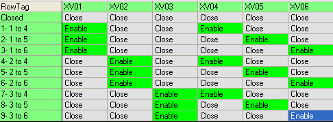
Well, let's look at what the Line can do if we give it some intelligence
We could make it respond to a request for a route, in this can one of the 6 possible routes.
Then we can make sure that the valves that must be closed are closed and those that are to be opened (by the source and destination,) are Enabled, meaning that the relevant tank has control and can open or close the valve. Here is a table showing what the 'Line' logic does


Note - it may even be possible for the Line module to find the route by some logic that works it out itself, but a simple table works in cases like this. 
Here we are in S88 terms

And we also need to establish some communications  between the source and destination unit.
This can also be done by the 'Line' common resource. There will be more to come


Thursday, 7 June 2012

Liquid Transfer Automation - Part 2

Overview

For any control we need measurements, effectors and some control algorithm - lets call it control logic. Letss look how there apply to a liquids transfer.

Typical Measurements are:

Source level or weight,
Destination level or weight,
Flow path confirmation – from limit switches on valves, flowplate switches etc
Pump status, flow meter readings etc

Typical Effectors are:

Discharge valve at source, inlet valve at destination
Flow path valve actuators
Pumps, control valves etc

Control Logic

To control a transfer, there are devices at each end, such as a discharge valve and a fill valve, pumps, pressurisation systems etc that should be controlled simultaneously.
The control logic needs to sets the devices in the route, monitor them, and determine the start and end of the transfer.
Here is a very simple State Transition diagram for a transfer.


We may also need consider such things as
Need to prime pumps before transfer
Need to drain, or blow line empty after transfer
In the case where the transfer is for dosing a specific quantity there may be need to allow for the 'in flight' material that will flow after the transfer is told to stop.
And we should always consider Exception handling 

Exception handling 

There are many things that can go wrong during a transfer, such as instrumentation, pumps or valves failing, control systems failure such as IO card failure, and even communications errors between the source and destination controllers. The control logic should be designed to handle this. Typically this would involve some logic that detects the failure and then sets the equipment to some fail state, this may well be the same as the Ready State.

Source and  destination coordination:

Now, it is very likely and good practise to have a separate program module to control the source tank and another to control the destination tank. (I will cover this more in future post.) 
It is also possible that the source is controlled by a different control (PLC or DCS) to the destination. Either way it means that we need to have an interface between the source and destination modules.
And I don’t think it right to have PC’s over a network having any real time involvement in this at all, I consider that this should be the domain of purpose designed real time controllers. PLC’s or DCS controllers for example. So this interface should flow on the control network controller to controller and not depend on communications with for example a batch manager.

Wednesday, 23 May 2012

Liquid Transfer Automation - part 1

This is about moving liquids from one tank to another, a frequent activity in plants but one that has little guidance from the s88 standard.

Specifically it is about transferring via pipes rather than for example by intermediate containers such as bottles, barrels etc.  In other words, the situation when we want to transfer some liquid from a source tank to a destination tank. This could be when we want to move an entire batch, or it could be when one tank gets a quantity dosed from a supply tank

The issue is what control is needed during the transfer, and where and how to apply that control,.

This will cover the physical equipment, the procedures to carry out a transfer and the control logic involved. It will also suggest an S88 module structure for the task and touch on the resources handling of transfer systems

It is the intention is to define a single method that covers the various type of transfers in the same way.

This is in my opinion one of the areas where batch projects, S88 based or otherwise, have had the greatest problems, most especially in the time taken to define, and then program the solutions.

But first let’s look at the general requirements in terms of process flows and the mechanics, the pipes, valves and other equipment used to establish the flow route.

Single Source and Destination


Multiple Source and Destination via Single  line

Now, putting pipework in for each route is expensive and impractical so an alternative is to share the lines, so here for example any of three source tanks can feed any of three destinations via one pipe.
This type (often found in brewing and dairy for example) can be made automatic.


This type involves manually setting the route using Flow plates - this ensures that liquids cannot contaminate each other, typical of pharmaceutical plants

Of course in this case (and assuming the batches must not mix) only one transfer is possible at one time.
More to come, please check back.

Added 7 June 2012 - there is a very interesting discussion following this post in LinkedIn

Wednesday, 1 February 2012

LinkedIn discussion Why do so many Automation Projects go wrong?

Recently there has been an interesting discussion on a couple of LinkedIn groups
You can find it for yourselves on the LI Groups (mostly the Automation and Process Control groups),  although that means that you may have to join them,
Why do so many Automation Projects go wrong?
From the Automation Group
This is a very broad subject to which there can be many different responses.
From my personal experience, I have seen automation projects fail for the following reasons :
1. Incomplete brief from the client.
2. Poor selection of equipment. Lack of experienced personnel making unsuitable
choices. Most common mistake is using complicated solutions. KISS principal is
paramount here.
3. Poor planning and scope of work. Again, lack of insight into what is required often
leads to an un-satisfactory conclusion
A general comment here : my credo has always been that I have always asked someone more knowledgeable than myself when in any doubt. Many automation practitioners believe they would disgrace themselves by doing this. The opposite is however true and normally leads to an improved solution.
----------------------------------

Following are my observations:

1.Lack of proper understanding of the "process to be automated" by the automation engineer

2.Improper sizing of Final Control Elements by the owner or their engineers.

3.Additions or revisions of I/O or functional requirements by client during FAT, pre commissioning or post commissioning stages or at SAT

4.Cutting corners by automation company to secure orders!

5.Foolish confidence on the part of automation engineer that he can conquer anything by his programming skills!

7.Wrong assumption by the client that "PLC or DCS" can do anything and everything and "Functional scope" can be expanded at any phase of the project!

----------------------------------

Although the above comments describe some key issues for failures, on a high level there is a serious gap with Automation Managers in adhering to basic project management principles. Most of the projects are executed merely depending on the historical information of the previous projects and the experiance of the project manager or lead rather than analysing facts. I would say that emphasizing on project management guidelines would highly reduce risk and calling out for project failures
----------------------------------

The points raised are excellent and show in-depth understanding of how easily things can go wrong : Taking the first of these, it IS so easy for an outsider to fail to come to grips with the dynamics of the Process when software and indeed, hard-ware are designed and chosen. One should always get an experienced Process professional skilled in the actual Chemistry of the plant to be automated to check out one's ideas. many of these could be flawed.
Then, despite the plethora of Valve sizing software available, my own preference has ALWAYS been to let the Valve manufacturer specify the actual size and trim of the valve in question. ( Fill in the valve sizing data form he provides ) Then if it does not work as per designe criteria, there is always a fallback position. I have worked in so many plants where my pre-decessors have installed oversized valves, that I am very wary of falling into this trap.
Once the design is accepted, the client needs to accept that "Design Freeze" has been reached ( formal milestone in the Project schedule) Any required divergence from this will cost HIM money.
The other points are equally relevant, but I will let others share their views,
regards,
----------------------------------
 • It's the lack of clear objectives and definition of the technical and commercial requirements. All the process elements, ranges of tolerances and the variables must be identified and addressed along with the costs and the timing for implementation to ALLOW for success - execution is another matter entirely!
An important point not touched on yet is the long term commitment the customer has to make toward automation. Even the best engineer cannot predict the changing business rules or develop a perfect design. This is especially important moving from a manual system for the first time as the entire business model and resourcing requires changing too.

I've seen many 'system failures' blamed on a few small component, miss-scoped elements or training issues that remain undefined and discredit the entire system.

I agree with Charles around the KISS principle and don't over engineer too soon you are sure to miss-scope and also the Design Freeze however... I recommend starting your improvement program from day one to allow all those scope changes to be collected and distilled. I'm a strong advocate of Agile PM techniques to allow the system to grow into the business rather than spend months fighting over spec's that will never stand up in court anyway...
----------------------------------
 From my experience, transforming the Project requirement into a System design is the key aspect of success for any Automation project.

An Automation system design should balance 1.‘Hardware modules (Instruments, motors/actuators, sensor/signal interfaces, etc…)’, 2.‘Software modules’ (UI, signal/image processing, control logic, etc…) & 3.‘Mechanical modules ‘(robot arm, fixtures, etc) in an accurate proportion.

A simple example; while designing a Vision system, when a limitation is hit on achieving a positional accuracy for a mechanical arm in positioning the Part under Camera’s field of view, the designer should know to what extend this deviation in position can be taken care by a suitable Camera selection or by Image Processing, with which an efficient system can be designed to meet the process/project requirement. In many instance, the Automation project will lead to failure only because of bad design or lack of expertise for designer.
The designer should have good experience/knowledge on all of 3 core components (mentioned above) to design an efficient automation system.

Sometimes the respective (Software, Electrical & Mechanical) engineers would step into the project development with assumption/over confidence and without having clear understanding on complete system requirement or other system modules that would lead to project failure in later stage of development or sometimes on deployment at the customer site.

From the Process Control Group
you only know what you know when you know it.
----------------------------------
when we do not give much attention to the fine details ,projects becomes difficult
----------------------------------
 From my experience, which is not breweries, there are a couple of main areas that have caused automation projects to be less successful (I hate to say fail). Poor planning up-front with no real vision to what the final product should be (not only look like but how it should function), is one of the first things that comes to mind. The other is not getting all the right stakeholders involved from the beginning to get their buy-in AND give them a sense of ownership.
----------------------------------
I have learned that any project can be managed correctly and will lead to the desired and working result if a good functional design is made and discussed with the client (or made by the client and discussed with the supplier). Also from this document a complete test protocol can be derived quit simple, so testing and approving an application is also easy and complete. The problem is that both supplier and customer have to really read and understand the document.
The document itself can be written in any language and does not have to be technical. It is more important to describe the complete behaviour including all (un)known situations which can be presented to the automation environment.
The choice of hardware and software to realise the solution should be made when the functional design is complete. This can lead to a technical design (for instance to break the software into pieces that can be handled by the team or to design a standard structure to use in all equipment).

In this way both customer and supplier have to invest time in the start of the project but it will definitely pay off in the end of the project (less problems, less discussions, less bugs, etc.). The project will run in a realistic time schedule.

I am afraid the article is pitched as a sales exercise and does little to elaborate on any best practice methodologies, software engineering or requirements engineering that are the silver bullets used to tame the wild beast that every project has the potential to become. Knowledge of an industry alone doesn't give you the skills to actually execute good projects!

If you want good pointers then read the software engineering books by Ian Somerville and Roger Pressman. Look at SWEBOK (Software Engineering Body of Knowledge) an excellent resource!

Don't forget to look at new methods such as SCRUM. Embrace requirements engineering and use good design practices coupled with sound quality assurance and project management.

Following the above doesn't necessarily guarantee a positive result, there is always the totally unexpected but.... ignoring the above will almost certainly cost you time and money and maybe the whole project too!
----------------------------------
I agree in part, although to be fair to René Leven his point is that the Process Expertise that his company can provide (in a specific area, brewing) is beneficial, and I don't disagree with that.
Also the software engineering methodologies that you mention are, like most of them, based in the IT world, and not automation, and I strongly believe that the two, while sharing some things, are different.
I mentioned my old "What goes wrong with batch process control system projects? "
www.controldraw.co.uk/presentations/frspaper.htm
It is a short version of a longer paper, and yes it promotes my software ControlDraw - which you could call a CASE system for requirements engineering but unlike IT systems like UML is actually orientated around automation. It is not orientated around a particular solution.
----------------------------------
Industry knowledge may appear to have benefits but it also has limitations as to its use. Knowledge gained by working on a project for most clients is often proprietary and cannot be readily divulged or utilised on another client's projects without first gaining the consent of the owner of the information often regarded as the intellectual property of that company. We know that most industries are competitive and as a result they defend their process knowledge with a passion and rightly so. After all companies often spend millions of dollars to obtain and perfect that knowledge.

I looked at the question of IT versus IAC software engineering methods a few years ago whilst writing my dissertation "Requirements Analysis in Industrial Automation & Control". I spent a couple of years researching similar topic(s) to the one driving this discussion and the results of my work are contained within that document. If anyone would like a copy then please drop me a line?

Since then I have used The UML as a design tool for a mining project in Australia and Structured Analysis on a project for Petro-Canada with great success. I modeled all of the PLC requirements for the mining project in The UML first and then developed the code templates in GE-Fanuc RX3i PACs. I have an example of this approach if anyone would like to see what I did?

I like ControlDraw and I think it is the best tool yet for modelling IAC specific projects and would recommend to anyone reading this article to try it. But at the same time I would also advocate using some of the methods described within the books I mentioned. They are written to cover IT and IAC related methodologies.
----------------------------------
And I think you used ControlDraw 1 in 1999. Believe me it has been improved beyond what you might even have imagined since then, and yes I have looked into UML and Structured Analysis methodologies a lot in the process of developing version 3.
Re the 'intellectual property' that you find in various projects, it is true that companies often defend it. I have hundreds of models from such projects. But when it comes down to it an awful lot of it (95%+) is virtually the same as other people do.
I would very much like to see your dissertation, you know my direct mail address.
And if you are ever nearby drop me a line.
----------------------------------

 My experience is based on spectroscopic/photometric process control.
First 10 years I had sometimes to learn the hard way and and I could see also at
other vendors of such instrumentations solutions had difficulties.
Sometimes it looks that there is a roll back in technology for some years, because the user
have so many bad experiences with few solutions.

The reason is, that big and small vendors try to offer a "product" or solution "as is" and this has to cover the clients application. This can not always works and depending the chosen product setup the risk for mismatching is higher or lower.

For this reason I left the original way to be a "instrumentation vendor" with certain products for sale a certain number every month or year .

Now I have a "building set" of the most critical things I have learned and I add around engineering, consulting, feasibility testing and assistance to choice the right components from third part vendors.

My experience now is, less trouble and mismatch!
Means more successful finished projects!
----------------------------------
 My experience is in the APC area and competing Honeywell, AspenTech, Yokogawa, and others is the bidding process is all smoke and mirrors. Clients have no idea what is needed in the bidding for a successful outcome.
----------------------------------
"is all smoke and mirrors." sounds tough, but confirms my opinion
if "dinosaurs" try to rule inovation ...
----------------------------------
 To develop a successful automation project should be first of all a functional description and a clear idea of the process to be automated.
After this have to develop the philosophy of control and select the technology that will make the solution. This technology must have a local representative (or at least on the same continent).
Along with a good electrical installation with the electrical protections well calculated should be made a good simulation of the system and a final test of acceptance with the participation of the client.
Prior to the commissioning of the equipment should be thoroughly reviewing installations and wiring terminations.
Other thing you don`t see in the books is that the more the client get involved in the project the more compromise he has to help and solve some issues we can have during the commissioning,so make the client active part of the project.
----------------------------------
 A final in-house test with simulation software can indeed be an eye-opener for the client and deliver a great saving in time in the delivery fase (and shorten the final acceptance test). Some of these simulation software are capable of simulating the hardware I/O, which has the advantage of minimal changing of the software (preferably no changing at all), thereby reducing the risc of bugs made by the adaptions for simultion to zero.
In this way both logic, control loops (for instance PID loops) and the look and feel of the Scada can be tested and experienced.
This will lead to more understanding of the proces and the solutions by the client and the supplier (due to the comments of the client).

Together with a functional description and a solid test protocol the automation part can not go wrong in this way.

Note that the electrical installation is made according to a set of electrical drawing which also has to be checked. An active client will demand these drawing in order to check them, before the supplier may proceed with the production of the installation.
The number of installations which are delivered and accepted without a complete or error free set of drawing is too large.
Both client and supplier are capable of changing this habit.

We must conclude that delivering a succesfull automation project needs both an active client and an active supplier.
The assistance of software to make documentation and check the working can be very useful, but is not the key secret for succes.
----------------------------------
 The most spectacular successes I have seen had committed champions to lead the various phases of the project who could readily accept going back to the drawing board to overcome any difficulties encountered during the execution and construction of the project
----------------------------------
In any automation, the wekest link is human being. So many new technologies /concepts/operating philospphies are evolving every day.the less we are trained/ updated, the more we fail. No woder, we should end up only in counting.
Thank you very much for the many interesting comments so far.
@Bob, I understand your concern about that the article is a little bit sales focused. However I liked this article written by my former colleague (I work in another field now) and wanted to support it. I am glad that it resulted in a discussion with many interesting and true comments that followed here in this thread.
I agree to many oppinions here that we should involve the customers as much as possible, know the technology and also mentioned inhouse tests can help increasing the projects success and having less stressful commissioning.
----------------------------------
Francis Lovering • It is interesting that this discussion has largely covered exactly the same things that have been known for years and years. Define the User requirements properly, involving the user closely, simulation testing, using modelling techniques and so on. But as I said all this has been known for years. And yet projects still go wrong.

I think that getting the right project manager and empowering them is one key. Among many other things such a manager needs enough technical skills to communicate both ways with the end users and the automation team. They are not common.

An issue that I have not seen mentioned here is one that applies to the frequent situation where an EPC engineers and buys all the equipment for the project including the automation system. Often the EPC produces the URS on behalf of the end user and sits between the user and the Systems Integrator. There are often complex interactions and sometimes conflicts between the EPC’s desire to ensure that the project is held to its cost estimates, and the end users desire to get exactly what they were hoping for.

Another major issue is Change and how to deal with it. Changes arise during a project for various reasons, often a part of the process is changed late and some parts are not completely definable until late in the project, after the system has been ordered. This is particularly true for fast track new process projects.

There are papers that address some of these points www.controldraw.co.uk/presentations/Presentations.htm

----------------------------------
I agree with Francis, but would like to add that there are 4 major items that need to be added to any project, Planning, Planning Planning and testing.
Planning with the sponsor or project initiator for the project, that he has defined what he wants to achieve.
Planning with the user, (often not the project initiator) that he gets what he wants.
And planning with the project delivery team, to ensure they develop an accurate functional spec meeting the needs of the first 2, then plan how to deliver ,review and test the system before delivery to site.
Finally Testing, commissioning the system properly, and testing the "What if" and What can go wrong scenarios not the what happens if it all works scenarios.

This takes time and costs up front, but no where like what it costs to fix later, however it depending on the environment it can be difficult to convince people of the real benefit of this approach especially in a multi disciplined environment where the overall cost means it gets little focus or understanding. However it does buy a lot of good will and acceptance of the project and its outcomes.
----------------------------------
This discussion is getting more interesting with every thread. I would also like to contribute by a background of five >million USD projects as a project manager at the user side.My assumption is; an automation project is either a reinstrumentation project or a project which is part of a bigger grass root project. I will concentrate on the first one.I think there are basically two types of customers; the ones who expects the contractor to create and submit the best project, and the ones who think that the contractor is only a tool to implement the described project. It is not usually black and white like I described above, but usually a mixture of behaviors. Second model usually helps more for successful projects, I believe.Since all the projects have two actors; i.e. the customer and the contractor, the 'agreement', and the succeeding 'communication between them' are the most critical and key elements with any project, especially in automation projects.When both parties' project managers are excited with the imagination of the project, and the agreement is good enough to handle unexpected issues, then we can say that there is a good probability of success.I will stop by a plain fact, before being boring; both parties spend a small fraction of the total intellectual effort involved in a project during the preparation phase, which will cause change orders or reluctant acceptance later. Therefore the main idea, the structure, expected performance should be clearly declared by the user, beside specifications, and database. The contractor should be transparent and specific during the bid.The following document presented in Vienna 2009 PALM Forum, is a short form of my experience on the topic. www.scribd.com/doc/43914146/Improving-Reliability-Thru-Automation-Projects-r3
----------------------------------
Haven't read all the experiences, but I had not seen many projects go wrong.
Almost always they end as expected.

Success=result-expectations.

May be lack of communication of between client/user expectations and manager/integrator objectives.
----------------------------------
We are developers of software for the manufacturing industry (mainly glass and joineries) and about 40% of our projects are factory automation. In my experience there are similarities with our other software projects in that it is almost impossible for the customer to come up with a good specification of his needs at the start. But while agile software development is a good answer to this problem in pure software projects, in factory automation projects the main costs are in the hardware and to change that part in a later stage is not easy and expensive.
However, if the customer becomes aware of his situation it is quite often easy to convince him to design a bit of flexibility into the machinery.
Furthermore we usually convince them as well to do only the basic functionality of our software first and then extend while we get experience with running the line. This has multiple advantages. First, the learning curve for the users is less steep. Second, the users can give us some input on their additional needs and will get improvements, which increases acceptance, and third it is always difficult for us to get proper interface specifications from the machinery manufacturers until shortly before they start installation, so the time window to adapt our software is usually very short, which means we prefer to deliver a smaller but properly tested subset than a final solution with lots of bugs.
----------------------------------
I completely disagree with the topic title , if it often fails I am sure automation would have been replaced. I also agree with Bob , this topic is clearly sales biased.
Automation is never a project on its own , it has many dependencies and interlocks with mechanical, pneumatic, hydraulic, IT , SCADA and people counterparts. If something is not well understood or prepared the automation guy has to adapt.
The problem is that the automation guy always comes last and gets the blame.
So yes we have to adapt and learn , projects live and need to be adjusted.
Don't get me wrong preparation is key but even then it doesn't go as expected, and then the automation guy has to write some funny logics to compensate for example the mechanical problem.
About 10 years ago something went very wrong in space because two mechanical parts did not match , the parts where made by two different companies ( all HAIL to the lowest bidder aleluhja) and they both used different tolerances. it was like one used metric and the other imperial .....so with many years and millions to prepare, enough people and skills it still goes wrong , but we learn and adapt.
----------------------------------
Francis Lovering
Not many people admit to problems with their Automation Projects, publicly at least.
And they tend to get there in the end, perhaps with less functionality than they originally hoped for and with overspends. So the project does not fail overall.
As for "and then the automation guy has to write some funny logics to compensate for example the mechanical problem.", this is a classic failing in the requirements analysis. And 'Funny Logics' are not a good thing to do.
Hans
You may think that " in factory automation projects the main costs are in the hardware", my experience is that there are many projects where this is not the case. And defining the hardware is relatively easy, it is in the software where the projects go most often wrong.
----------------------------------
Francis Lovering - 1st paragraph, BINGO! Exactly what I was trying to say, to answer the original question.
----------------------------------
I agree with you. Automation (Control and Instrumentation) is the last discipline in any project that has to make the project come to its final realisation and always suffers from project cut backs and or discounts. In my experience, automation has always suffered from budget cuts and shortcut. Other engineering disciplines always get their way when it comes to forging a 40" flange or construct a giant piping support with almost a near blank check, just because they are buying a big lump of metal, but if you try to get an extra piece of software license or, more advance control system, getting an extra 1000 dollars is like getting blood out of stone.

In a recent documentary on worldwide resources, one international recruiter stated "If you pay peanuts, you get monkeys", and worst still any monkey with keyboard claims to be control system programmer, just because they happen to learn a few graphic game codes in VB, and all of a sudden they are expert DAQ/SCADA programmers.

This has give automation a bad name in so many industries to a level where human intervention is still seen as safer bet than automatic alarm on a high pressure drill return flow line. And when the operator is fallen asleep on the job which has lead to the rupture and release of effluent into the environment inflicting 100s-1000KUSD of damages, they just record it as human error on their LTIs and lessons learned, as an acceptable practise.

----------------------------------
Francis, of course you are right, in most cases the software costs exceed those of the hardware. This simply reflects the fact that these days all the complexity is addressed in the software. What I should have said is that most providers have the software in some form already; all that’s needed is some adaption to the actual situation.
In our case we only do the overall control of the plant. That is we make sure the right pieces are produced at the right time and arrive at the right point for assembly. To this end we communicate with the machines’ PLCs which are supplied and programmed by the machinery manufacturers. They of course are in the same situation as we are. They have some form of software from previous projects which they have to adapt to the new plant.
In my experience that is where the problems come from. Quite often the customer starts building the factory before they have definitely decided on the machinery suppliers. So we know the details of the machinery and the interfaces to the PLCs only a short time before the machinery is installed. And because the PLC programmers have as little time as we have to do those program adaptions, these interfaces might even change later, because we or they discover problems in the communication.
Thus, although those program extensions usually only take a few man-months we have too many programmers involved on both sides trying to make it work in the short time given. This means a lot of communication overhead with a high potential of misunderstandings. These are then usually discovered during implementation and testing, where you are faced with other problems as well, e.g. machines not yet working properly and of course a customer that does not understand why the whole thing is not working yet.
This brings me back to the point I tried to make before. For a first version, try to implement and install the minimal functionality needed to make the plant work in the standard case. Implement additional functionality later. Usually the customer learns only after a while what all they could do with that new plant. Just recently we had a case where during specification we all agreed, that a certain configuration would never happen on that new production line. It just did not make sense to produce that there. Only half a year of running that line now the customer wanted to run exactly that and it suddenly made sense to all concerned. Fortunately it took us only a few hours to implement the software extension required to make that work.
Maybe this is a way of lowering the customer’s expectation of what they can get initially. But what they get in return are higher flexibility for changes and extensions later in the life of the plant and thus more possibilities in changing ad adapting the line to changes in demand, a changing product mix and new product to be produced over the line.

Note - the discussion is still running, and more points have been added, mostly repeating points that have already been made.

Tuesday, 24 January 2012

A New Automation Company in the UK

My long time colleague, Andrew Knott has now started his own automation company.

Knott Automation Projects Limited.

They will be able to provide full life cycle automation and information system consultancy services in the process industries. And they have deep experience with ControlDraw and S88 projects. Do take a look!

Friday, 13 January 2012

Objects contained in P&ID's compared with ControlDraw models

The diagram below shows how ControlDraw models contain far more then conventional CAD, notably the higher levels of the Automation Objects. Click to see full size.

Tuesday, 27 September 2011

Example of a ControlDraw P&ID for a BioFermenter

The diagram below (click for full size) is a 'typical' BioReactor as found in bio pharma plants. This diagram was produced in ControlDraw.

Tuesday, 12 July 2011

Process Engineers and the P&ID

This is a recent conversation that  I started on the LinkedIn
As the IChemE (Institution of Chemical Engineers) group is closed, non members of the group cannot see this dialog so I have posted it here.

Francis Lovering 

Piping and Instrument Diagrams are generally large and quite complex. 
They contain a lot of information, some for the equipment engineers, some for the mechanical and piping engineers, some for instrument engineers, electricals etc. 
Typically they have to be A1 or even A0 to be readable, such is the level of detail.
They are generally sketched out and subsequently marked up using pencils and a highlighter by the Process engineers. Then they are actually committed to CAD (once upon a time it was paper) by CAD draftspeople, not by the Process engineers.
I am interested why the Process Engineers do not normally do the CAD themselves.
Is the reason for this that the CAD software not easy for the process engineers to use? 
Why the marking up on paper? Is it that screens cannot yet compete with an A0 P&ID?

Alex Chatwin 
The reason why process engineers should not be doing CAD is a matter of time. What would you rather a process engineer be doing? Cad work or doing process engineering? Where is the best benefit for the company that is employing the process engineer. In Aberdeen rates for Cad work is in the region of 35 to 50 GBP; Process can be paid 45 to 75-80 GBP. Where would you spend the limited number of hours for the process engineer? 
I have seen both process engineers doing Cad work and cadders doing Cad work. If the process engineer indicates what he wants drawn then the CAD draughtsman can do a better job of the Cadding. Use the talents of the Process Engineer in assessing the important process critical areas. 


Kophyo Win
Computer screen limit your view of PID to a small area, making it difficult to be aware of impact on other parts of the process. It is easier to have a global view of the entire process on a large piece of paper and better for team work too.

Francis Lovering • Alex 
How about if the CAD actually made it easy for the process engineer? I mean do they get secretaries to update their spreadsheets and documents. These days? If the CAD was process engineer friendly (and the process engineer more, shall we say, adventurous) much of the drafting process could be eliminated. That saves money. 


Kophyo 
The thing is that the amount of detail on most P&ID’s actually obscures the bigger picture. You cannot see the wood from the trees 
And all those links between P&ID’s (the To and From connectors) make it a real pain to actually work out how major equipment items connect, which is what the global view needs. 
I feel sure that there must be some process engineers who do the CAD!


Alex Chatwin 
Francis,I have been in a company that employed Process Engineers as those responsible to do CAD. It doesnt work. We were using IPID 2010 and there was a requirement for the process engineers to have a very good understanding on CAD operations. This software would require the engineer to put in all the raw design information. I would rather that a process engineer received a printout on A3 of a template and make the modifications he wanted by hand. It is much easier to draw something by hand on paper then to input the modification electonically. The time by the process engineer wasted is large otherwise. In this company where I worked I had convinced the senior management that it was better to hire some CAD resource than tying up the process engineers. Keep process engineers doing Process Engineering. This is how the process engineer will be more productive. Also as a process engineer, the impact that I can make with the knowledge I have is huge. If we use process engineers to do CAD we are watching the Pennies and not watching the Pounds so to speak.
Alex Chatwin • In regards to having lots of connections, and a P&ID being complicated, this is why you have experienced process engineers that have seen alot of systems before. I have been looking at a gas import problem on an FPSO and the process flows spanned many P&IDs. It doesnt help me in my ability to use CAD to solve the problem. I need to ensure that what is happening is safe and it is technically competent. 
Please do not ask process engineers to do CAD as they have been at university in some cases for 7 years. This is not how to best utilise their time.


Francis Lovering 
All good comments, thanks. I am interested in the whole life cycle of the P&ID, and one thing that has not been mentioned is how they start. Before the P&ID there are Process Flow Diagrams, again I have often seen them done the same way. But as these are simpler documents would you agree that they are more amenable to being produced by the Process Engineers? 
I just want to comment about P&ID's from the perspective of an Automation engineer. 
As I mentioned, it is hard to see the wood from the trees. Only a small portion of the each P&ID’s is about control and instrumentation, so it takes time to get the picture. Generally a talk with the Process Engineer will of course save a lot of time. 
The is a huge variability between projects as to the content of them. For example some will squeeze a lot of equipment onto each while others will have more P&ID’s with each devoted to a primary equipment item (a Unit in S88 terms) . 
Some will show details that others do not, for example each limit switch and solenoid for each valve (3 or 4 balloons per valve) others will show one balloon with a key of some sort to indicate what the valve includes. Some will attempt to show the control loop details and others will not, some show interlocks and some indication of logic functions others do not.
As for the interconnections it is generally one of the first things I try to understand – it would be great if people produced an overview diagram showing the P&ID’s as boxes and the lines connecting them - but it is rare. Often the control engineers have to work that out in order to, for example, design the plant overview graphics and work out the overall flows and the interfaces between equipment (an important part of the functional requirements). 
And almost invariably the diagrams are not up to date (the true master being the marked up one that sits on the process engineers desk) 
Often P&ID’s are used as a basis for the graphics on the Process Control System, however that is rarely a consideration for the process engineers when producing them.


Alex Chatwin 
Process flow diagrams (PFD) are there to describe the process flowrates, the pressures and the temperatures. The composition and density of the streams will also be covered. This is the original design basis for the process and it is the normal starting place for process engineers. 
After the PFDs have been generated, the P&IDs will be developed. They start life as a blank piece of paper and intially a red line markup will be made. It may be that this occurs for a feasibility study but not a concept study. There may be several options all of which will be P&IDed. Once the design has been confirmed during the early stages of FEED the design will be set in stone and they will advance through several internal revisions to a final product at FEED. These will then be reviewed at early Detailed Design and modifications will be made. There is naturally much variability in the process depending on the level of complication of the project and the company that is doing the design work. 
The types of valve annotations will be different depending on the company developing the P&ID. My humble view is that P&IDs are not commercal purchasing documents and should be made appropirately simple to represent how the system works. If an ESD valve has two soleoids on it, if the type of valve is described in a legend this is fine. 
These are my views and I am sure there are process engineers who may disagree. 


Francis Lovering 
Alex 
I do know about PFD's do the ones here show what you mean? 
http://www.urswriter.com/index.html?ProcessFlowDiagrams 
(Please comment on them so I can improve them.) 
Part of my point when applying the term lifecycle to P&ID's is that they do not start from a blank piece of paper, don’t they start from the PFD’s? 
The lifecycle that conventional plant CAD products follow tends to lose this. I am unaware of any CAD products that can connect the PFD’s to the P&ID’s - if you know of one please let me know. 
As you describe, early stage P&ID's may change a lot (“There may be several options all of which will be P&IDed”) 
Would it be reasonable to say that at this point the P&ID’s are actually quite simple, and do not need CAD Skills?


David Greene 
I would prefer to do the initial P&IDs myself. With the use of libraries of blocks, it is relatively easy to create PFDs and then transform them into P&;IDs. Simple drawings are easy but most people are using layers and intelligence that involve a much better understanding of the software then I have. So, even when I used designers to draw the real P&;IDs, my preference is to sketch them out in CAD myself. 
Ideally a PFD is on a single sheet of paper while each P&;ID should be limited to a single major equipment item or system to facilitate number and allow room for the instrumentation. Back when we were developing Engineers, the thought was that a process engineer would do the drawing and data entry. I'm sure David Cockshoot could tell you a lot more about this.


Alex Chatwin 
My preference would be to ensure that process engineers are doing process engineering. WIthin a design house there are so many other tasks that are important for the process engineer to do that they should not be wasting their time CADing. A simple Red Line Mark up will suffice and let a Draughtsman do the drawing. If a process engineer is required to persuade regarding a process idea then it may be appropriate for them to sketch out options. This is as far as a process engineer should take it. Fiddling around with blocks and juggling them around space wise is the realm of the draughtsman. We have to ensure that what is there is correct. Safety, isolation philosophy, emergency shutdown and control philosopy, blowdown and flare assessment, line lists, valve lists, pressure drop calculations, heat and mass balance and this is just a few tasks. These are what the process engineer should be doing, not the drawing.


Francis Lovering 
I was peripherally involved with Dave Cockshoot in the early days of Engines (which ultimately became part of AVEVA) so I know the history. 
I believe that the idea " the thought was that a process engineer would do the drawing and data entry" was fine but the implementation awful. 
As is clear Process Engineers have too much else to do to become proficient in CAD Software. But I don’t see that as preventing them from using something simpler at the early stages of a project when all that detail is not needed. 
Part of my intention in this discussion is to research how I can make my software, ControlDraw, into a product that Process Engineers Can use in exactly the way you describe. 
It may never be suitable for large P&ID's, but I think it is already more than capable of producing PFD's and much more, including simple P&ID’s that could be used as a starting point for the CAD versions. 
To explain my thinking I have put a diagram here 
What do you think?

David Greene 
I did take a look at your drawings and they do show the sequence of drawing development but as discrete documents rather than a continuum of developing process drawings. 
I used Vizio for PFDs and conceptual P&IDs. Several times I tried to do something like you suggest with Vizio and also with SuperPro but was not successful. 
We really need a way for the draft to flow into the real P&;ID without losing the initial work. I like the idea of showing relative elevations and sizes on P&IDs, matching lines from P&ID to another, showing remote/computer control/instrumentation away from the equipment, etc. My experience, particularly with batch processes, is that the instrumentation/control representations take up too much space and need to be simplified. In some cases, you can start with very sophisticated controls because its just like something done previously but in other cases, the process design benefits from a progressive development of control steps and then there is the case of cloning an entire process with minor changes which is more amenable to the red lining described by others.

Francis Lovering 
David
You should try with ControlDraw rather than Visio, I would be very willing to help you


Visio :
  Prettier
  Made by Microsoft


ControlDraw :
  Designed for our industry
  Hierachical
  Variants - multiple versions of the same diagram with different tag numbers, exclusions etc
  Intrinsic State Model - supports Simulation and such things as Equipment State Matrices
  Simulation - put diagrams into run mode, see process flows etc
  Library of objects 
  Easy to re-arrange, moving objects from one diagram to another for example
  Intrinsic Process Database (eg Equipment List)
  Intrinsic version controls
  Hundreds of diagrams in the same model all linked
  Drop a Valve into a line without having to connect it
  Free Viewer with Comment capability


Edmund Fish 
I think the problem is that when I started it was skilled draftsmen that did your drawing and they were still a separate breed because CAD had a steep learning curve. But I noticed on the times when I had drawn P&;IDs from scratch that when the draftsman ran over it looked a lot better than my best efforts. That skill in making a drawing clear goes beyond just P&IDs and applies to other drawings. BUT today we have more and more "CAD jockeys" that are little more CAD secretaries; they draw on CAD exactly what get given on paper. 
Process Engineers bring so much more to the table that having to learn a large skill set (as distinct from transferring one on to a spreadsheet of word processor) is just a poor use of of everyone's money. I can use a word processor / desktop publishing software but I have friends that are old school printers and the subtle changes that can make to a document can sometimes amaze me. 
Adam Smith argues that economic progress comes with increasing specialisation; process engineers doing CAD work is a step backwards.


Jon Baker 
I agree with the thread running through this. I don't think its a good use of process engineers time and I think the product they would produce would be inferior than one produced by a good CAD operator. But thats from the perspective of a reasonably sized design office - may be different in a smaller organisation. 
My experience of drawing up PFDs in visio or similar is that the CAD people need to start again, because it doesn't have the finesse or intelligence of a proper CAD system. 
On the other point of drawing size, we always try to make our drawings readable at A3. It is about deciding on how much to put on a single drawing.


Ken Rollins, FIChemE 
I agree with the use of Process Engineers time, but that being said, a CAD-literate process engineer can produce a first draft of a P&ID quicker than he can sketch it. Thereafter he should not waste his time adding instrument tags, line numbers and the mass of semantics that go on these drawings - leave it to the CAD technicians. There is, of course, a more sinister reason. Most clients have definitive CAD standards to do with drawing layer, X-references etc, line weights, font types and sizes etc. A good CAD co-ordinator is required for all of this, and that is not the function of a process engineer. 
I endorse what Jon has said about smaller plots being perfectly OK. Use more drawing sheets and make them less cluttered.


Jiri Salek 
Our CAD draftswoman works for 10-20 process engineers. She is the best I've ever seen. What she does in one hour takes 2 or 3 hours to other CAD guys. How is it possible? She is specialised process draftperson with 15 years experience. I can produce sketches in visio or similar but there is no way how process engineer could efficently draft PIDs. 
Perhaps just updating a text during the review process or adding dates and signatures for the final issue could be efficient.

Adeline Hoo 
This is an interesting topic. I have been a Process Engineer in a multinational engineering firm, no, they don't allow Process ENgineer to CAD, we could only comment and guide the dedicated draftsmen/process designer to CAD. 
Now that I'm in a much smaller company, my project manager made me do everything, literally from conceptual design to creating P&ID from scratch using AUTOCAD which I've not much experience, but once you're pushed, you'll pick it up. 
I'm wholly involved in the process part of the project at the least, designing the systems, putting them onto P&ID (from scratch I stress), generating the subsequent component lists...quite taxing but worthwhile. 
But then, it's a relatively smaller project that I'm doing in a biopharmaceutical line, if it's a big one, I prefer dividing the process design and mere drawing work is better.


Francis Lovering 
Thanks everyone who has participated. 
I would like us to summarise the conclusions of this 'meeting of minds'. 
My Conclusions. 
Process Engineers have a range of activities to perform that mostly makes it inefficient for them to learn and deploy CAD systems like AutoCAD or even Visio for detailed P&ID’s 
Some like to use Visio, or even AutoCAD in the early stages of projects. 
Process Engineers are capable of doing the drafting themselves if they have to. (I wonder about this, would I be wrong to imagine that the ones they do may have drafting typos but a better process perspective – can a diagram show a perspective?) 
Some of you would prefer to do the primary process diagrams yourselves, before handing it over to CAD Specialists 
A Possible conclusion is that P&ID’s need rethinking, they are after all based on a paper model that goes back half a century or so.

Alex Chatwin
Francis, I do not think that the current system needs to be re thought The current system works with the correct work procedures. 
I have seen during my time, a range of activities from Process Engineers doing Cadding and others where the infrastructure to do simple updates makes it un workable. The most important ascept to P&;IDs is work flow. It is important to place the level of responsibility at the right level to those that can make a difference in the most effective manner. Process Engineers are responsible technically for P&Ds and it is important to use the technical competency of daughtsmen to ensure that they are drawn correctly. 
if it aint broke dont fix. 


Francis Lovering • Alex
As I said, a 'possible' conclusion. The current system is certainly not perfect, procedures help to make it work, but it could be improved. In particular to retain the links back to the fundamental process - the Recipe.
And actually process engineers are not 100% responsible for the P&ID's, many other technologies contribute to their development. Arguably cluttering them up and obscuring the fundamental process as they do so. As a control engineer who has been using P&ID's for about 35 years I find it painfully slow to extract the stuff I need from most of them, although there are some exceptions. It might be a good topic for a new discussion - what should the Scope of a P&ID be, how much of the control should it show, how much detail of the piping and so on.
One good thing about P&ID's with good procedures is that they provide a sort of workspace where the engineers from the various technologies collaborate. But is that the most effective way to make that happen?
15 days ago

Alex Chatwin • Francis,
In the oil and gas industry, this is my field, process engineers are responsible for P&IDs, Cause and effects and input into Alarm and Trip setpoints. It is up to us to say how we want it to work. It is then up to the intrumentation engineer to ensure that it works how we want it to. As I was explaining before, once the design of the system and the design set, early to mid FEED, there will be an opportunity for all disciplines to input their comments into the P&ID and this is called an Inter Disciplinary Check, IDC This is always should be done prior to a release to the client and/or before a HAZOP.
For modifications to process systems, everywhere where I have worked, the Process Engineer is responsible for ensuring that Brownfield Work is reflected on the P&IDs correctly. Brownfield meaning modifications to existing installations. There is alot of information to show on a P&ID and should not be the only source of information. The Cause and Effects are a good source together with the Alarm and Trips for figuring out how a system is meant to work. There should also be a Operations Narative together with operational procedures. Often it is the case during commissioning that the set points need readjustment and reconfiguring to ensure smooth and safe operation and the troubleshooting will be the realm of the ops process engneer who then provides feedback to the instrumentation engineer for the required changes. There will be a whole bunch of input at this stage. However, the process engineer needs to ensure that all recommended changes will be acceptable and not introduce additional risk to personnel and secondary to assets.
In my experience, the main criticism I have would be the work flow management in P&ID development. The level of responsibility has to sit firmly where it can make the most impact. It is up to to individual company to decide on the level of detail shown and how much information to show on one P&ID. This will be part of the IDC.


As you can see in the oil and gas industry there is much more for the process engineer to be doing that has a very hgh impact. Another reason to why he should not be sidetracked by drawing.

Joyce Jabane
As a process engineer, CAD is the best thing that happened for development of P&IDs. With AUTOCAD 2011 and ; 2012, it will reduce the time required to carry out designs. For instance, if P&ID is drawn in AUTOCAD 2011, it will be easy to generate the GA, isometrics, structural and civil designs from it. Based on my experience, it will however take longer to develop the P&ID, but less for other drawings metioned.


Juan Cuba 
Very interesting topic. I can only say that actual Engineers need to be familiar with CAD/AutoCAD, CHEMCAD and use them according with the size of the project as tools. I agree with Alex, process engineers must be dedicated to do engineering and not drawings.


Alex Chatwin 
I agree we have to have an awareness with it as this helps us guide what we desire. Our tasks have a higher impact that just drawing. Leave CAD firmly in the capability of daughtsmen. They are better at it as they specialise in this area. 


Red-lined marked ups should be made by the process engineer as quickly as possible. Here is a rough summary of some of the tasks he/she will have to do: 


Design Philosophy - temperature and pressure. 
Isolation Philosophy 
Process Flow Diagram - to include heat and mass balance 
Equipment Datasheets - preliminary and detailed at later stages 
Calculations - Pressure drops 
Line Lists 
Valve Lists 
P&;IDs red-lined markups 
Cause and effects 
Alarm and Trip Setpoints 
Cv Calculations 
Control and Safeguarding Philosophy 
Flare Study and PSV sizing 
Operational Procedures. 


So to add to this list of very important activities, drawing, I will let you decide. 

Keith Plumb 
I do not work in Oil and Gas but mainly in pharmaceuticals and fine chemicals with largely batch processes. It never ceases to amaze me how much time is spent on P&IDs both process and CAD time.
Actually I think the P&ID is very broken and a serious rethink is required. I used Francis's ControlDraw to carry out the process design and to produce the P&IDs. I thought the software was good but could be better. I also thought it helped the process engineers and control engineers to get their thoughts together.
Sadly the client did not like the result - they wanted conventional P&IDs and my fellow process engineers were not that convinced. For me the generation of the P&IDs feels like the tail wagging the dog and it become a hugh task that should be much easier to do.
Francis when I get the time I would like a serious long chat about this.

Piotr Janowiak 
Generally I agree with Alex, but ... 
In many cases IDC is done by senior engineers on quite high level of generalisation. 
There is a zone where tasks of chemical or/and process engineer may coincide with tasks of other specialists e.g P&ID. The point is that P&ID is just a tool, a way how process engineers share information with other engineering departments. A process engineer must have much wider and deeper knowledge about piping or instrumentation if s/he has to prepare P&ID by him/herself. Reluctance of many process engineers to P&ID is incomprehensible. 
A process engineer is the pivot of project. Project information starts and has a source there. This discussion is really about who should know (and understand) more. The question is whether a process engineer should know and understand more about control and instrumentation or a control and instrument engineer should know and understand more about (petro-/bio-)chemical process. 
I think that such kind of multidisciplinary approach is needed from all specialists. 
Most problems which occur during start-up and commissioning have their source in the lack of communication between a process engineer and other specialist. 
For example - a process engineer specified on P&;ID that wanted to measure the liquid level. So s/he gave liquid name (e.g. produced water) and "all" physical parameters to an instrument engineer. I just wonder how an instrument engineer should know that produced water is not some kind of industrial water but the mix of water and HC, how s/he should know that a process engineer decided to add antifoam agent which is stick and may build-up on the sensor. 
It is not important who will draw P&ID. What is really important is what information a process engineer is going to share with others. 
Software such as ControlDraw can help, but a process engineer must understand her/his role in the project.


Alex Chatwin
 Please let me define responsibility. This means that Process Engineers have the final approval on P&IDs. It is not that we do this task solely on our own. I agree whole heartedly with Piotr. This is how we ensure that the right information is communcated to other disciplines. 
I have come across a major failing recently where the right service was not described for a valve. This has caused that the valve materials were not scoped properly. This comes down to the process engineer not having enough experience/time to get this right. This has lead to a major failing of a process system involving several hundred thousand pound failure. 
IDC should be trying to get everyones comments regarding the design to hopefully pick up these issues. 
P&IDs work but the work flow and where the repsonsibility sits to get the overall design correct needs careful evaluation and each organisation is unfortunately different.

Francis Lovering 
Alex, thank you for describing the process engineering activities so well, One point I would like you to consider is how well all those tasks are integrated by your CAD systems. 
For all the lists I would hope that your CAD can actually generate these from the Lines, Valves etc on the P&ID’s 
A very simple question is what happens if a tag name changes? Does that change propagate to all the documents you produce? 
Another would be the Cause and Effect diagrams – do these connect to the P&ID in any way other than manually? 
And Keith 
It’s good the hear about your project and I am sorry to hear that the client would not buy into ControlDraw, I know this happens a lot, not just for P&ID’s either. 
I do agree that ControlDraw cannot really produce P&ID’s like the industry is used to. It was never my intention for it to do so, in fact I started as you know from a completely different perspective – defining the automation. 
But at the front end of a project as you have found it can do enough, for example for PFD’s and then basic P&ID’s for the conceptual and front end engineering project stages. 
Now, if you start your project with simple P&ID’s such as those ControlDraw can do it provides a jump start that can be used first when you commit to CAD and secondly for the Control Engineering activities. 
I still think that the P&ID document model is overloaded.