
Tuesday, 27 September 2011
Example of a ControlDraw P&ID for a BioFermenter
The diagram below (click for full size) is a 'typical' BioReactor as found in bio pharma plants. This diagram was produced in ControlDraw.

Tuesday, 12 July 2011
Process Engineers and the P&ID
This is a recent conversation that I started on the LinkedIn
As the IChemE (Institution of Chemical Engineers) group is closed, non members of the group cannot see this dialog so I have posted it here.
Francis Lovering
Piping and Instrument Diagrams are generally large and quite complex.
They contain a lot of information, some for the equipment engineers, some for the mechanical and piping engineers, some for instrument engineers, electricals etc.
Typically they have to be A1 or even A0 to be readable, such is the level of detail.
They are generally sketched out and subsequently marked up using pencils and a highlighter by the Process engineers. Then they are actually committed to CAD (once upon a time it was paper) by CAD draftspeople, not by the Process engineers.
I am interested why the Process Engineers do not normally do the CAD themselves.
Is the reason for this that the CAD software not easy for the process engineers to use?
Why the marking up on paper? Is it that screens cannot yet compete with an A0 P&ID?
Alex Chatwin
The reason why process engineers should not be doing CAD is a matter of time. What would you rather a process engineer be doing? Cad work or doing process engineering? Where is the best benefit for the company that is employing the process engineer. In Aberdeen rates for Cad work is in the region of 35 to 50 GBP; Process can be paid 45 to 75-80 GBP. Where would you spend the limited number of hours for the process engineer?
I have seen both process engineers doing Cad work and cadders doing Cad work. If the process engineer indicates what he wants drawn then the CAD draughtsman can do a better job of the Cadding. Use the talents of the Process Engineer in assessing the important process critical areas.
Kophyo Win
Computer screen limit your view of PID to a small area, making it difficult to be aware of impact on other parts of the process. It is easier to have a global view of the entire process on a large piece of paper and better for team work too.
Francis Lovering • Alex
How about if the CAD actually made it easy for the process engineer? I mean do they get secretaries to update their spreadsheets and documents. These days? If the CAD was process engineer friendly (and the process engineer more, shall we say, adventurous) much of the drafting process could be eliminated. That saves money.
Kophyo
The thing is that the amount of detail on most P&ID’s actually obscures the bigger picture. You cannot see the wood from the trees
And all those links between P&ID’s (the To and From connectors) make it a real pain to actually work out how major equipment items connect, which is what the global view needs.
I feel sure that there must be some process engineers who do the CAD!
Alex Chatwin
Francis,I have been in a company that employed Process Engineers as those responsible to do CAD. It doesnt work. We were using IPID 2010 and there was a requirement for the process engineers to have a very good understanding on CAD operations. This software would require the engineer to put in all the raw design information. I would rather that a process engineer received a printout on A3 of a template and make the modifications he wanted by hand. It is much easier to draw something by hand on paper then to input the modification electonically. The time by the process engineer wasted is large otherwise. In this company where I worked I had convinced the senior management that it was better to hire some CAD resource than tying up the process engineers. Keep process engineers doing Process Engineering. This is how the process engineer will be more productive. Also as a process engineer, the impact that I can make with the knowledge I have is huge. If we use process engineers to do CAD we are watching the Pennies and not watching the Pounds so to speak.
Alex Chatwin • In regards to having lots of connections, and a P&ID being complicated, this is why you have experienced process engineers that have seen alot of systems before. I have been looking at a gas import problem on an FPSO and the process flows spanned many P&IDs. It doesnt help me in my ability to use CAD to solve the problem. I need to ensure that what is happening is safe and it is technically competent.
Please do not ask process engineers to do CAD as they have been at university in some cases for 7 years. This is not how to best utilise their time.
Francis Lovering
All good comments, thanks. I am interested in the whole life cycle of the P&ID, and one thing that has not been mentioned is how they start. Before the P&ID there are Process Flow Diagrams, again I have often seen them done the same way. But as these are simpler documents would you agree that they are more amenable to being produced by the Process Engineers?
I just want to comment about P&ID's from the perspective of an Automation engineer.
As I mentioned, it is hard to see the wood from the trees. Only a small portion of the each P&ID’s is about control and instrumentation, so it takes time to get the picture. Generally a talk with the Process Engineer will of course save a lot of time.
The is a huge variability between projects as to the content of them. For example some will squeeze a lot of equipment onto each while others will have more P&ID’s with each devoted to a primary equipment item (a Unit in S88 terms) .
Some will show details that others do not, for example each limit switch and solenoid for each valve (3 or 4 balloons per valve) others will show one balloon with a key of some sort to indicate what the valve includes. Some will attempt to show the control loop details and others will not, some show interlocks and some indication of logic functions others do not.
As for the interconnections it is generally one of the first things I try to understand – it would be great if people produced an overview diagram showing the P&ID’s as boxes and the lines connecting them - but it is rare. Often the control engineers have to work that out in order to, for example, design the plant overview graphics and work out the overall flows and the interfaces between equipment (an important part of the functional requirements).
And almost invariably the diagrams are not up to date (the true master being the marked up one that sits on the process engineers desk)
Often P&ID’s are used as a basis for the graphics on the Process Control System, however that is rarely a consideration for the process engineers when producing them.
Alex Chatwin
Process flow diagrams (PFD) are there to describe the process flowrates, the pressures and the temperatures. The composition and density of the streams will also be covered. This is the original design basis for the process and it is the normal starting place for process engineers.
After the PFDs have been generated, the P&IDs will be developed. They start life as a blank piece of paper and intially a red line markup will be made. It may be that this occurs for a feasibility study but not a concept study. There may be several options all of which will be P&IDed. Once the design has been confirmed during the early stages of FEED the design will be set in stone and they will advance through several internal revisions to a final product at FEED. These will then be reviewed at early Detailed Design and modifications will be made. There is naturally much variability in the process depending on the level of complication of the project and the company that is doing the design work.
The types of valve annotations will be different depending on the company developing the P&ID. My humble view is that P&IDs are not commercal purchasing documents and should be made appropirately simple to represent how the system works. If an ESD valve has two soleoids on it, if the type of valve is described in a legend this is fine.
These are my views and I am sure there are process engineers who may disagree.
Francis Lovering
Alex
I do know about PFD's do the ones here show what you mean?
http://www.urswriter.com/index.html?ProcessFlowDiagrams
(Please comment on them so I can improve them.)
Part of my point when applying the term lifecycle to P&ID's is that they do not start from a blank piece of paper, don’t they start from the PFD’s?
The lifecycle that conventional plant CAD products follow tends to lose this. I am unaware of any CAD products that can connect the PFD’s to the P&ID’s - if you know of one please let me know.
As you describe, early stage P&ID's may change a lot (“There may be several options all of which will be P&IDed”)
Would it be reasonable to say that at this point the P&ID’s are actually quite simple, and do not need CAD Skills?
David Greene
I would prefer to do the initial P&IDs myself. With the use of libraries of blocks, it is relatively easy to create PFDs and then transform them into P&;IDs. Simple drawings are easy but most people are using layers and intelligence that involve a much better understanding of the software then I have. So, even when I used designers to draw the real P&;IDs, my preference is to sketch them out in CAD myself.
Ideally a PFD is on a single sheet of paper while each P&;ID should be limited to a single major equipment item or system to facilitate number and allow room for the instrumentation. Back when we were developing Engineers, the thought was that a process engineer would do the drawing and data entry. I'm sure David Cockshoot could tell you a lot more about this.
Alex Chatwin
My preference would be to ensure that process engineers are doing process engineering. WIthin a design house there are so many other tasks that are important for the process engineer to do that they should not be wasting their time CADing. A simple Red Line Mark up will suffice and let a Draughtsman do the drawing. If a process engineer is required to persuade regarding a process idea then it may be appropriate for them to sketch out options. This is as far as a process engineer should take it. Fiddling around with blocks and juggling them around space wise is the realm of the draughtsman. We have to ensure that what is there is correct. Safety, isolation philosophy, emergency shutdown and control philosopy, blowdown and flare assessment, line lists, valve lists, pressure drop calculations, heat and mass balance and this is just a few tasks. These are what the process engineer should be doing, not the drawing.
Francis Lovering
I was peripherally involved with Dave Cockshoot in the early days of Engines (which ultimately became part of AVEVA) so I know the history.
I believe that the idea " the thought was that a process engineer would do the drawing and data entry" was fine but the implementation awful.
As is clear Process Engineers have too much else to do to become proficient in CAD Software. But I don’t see that as preventing them from using something simpler at the early stages of a project when all that detail is not needed.
Part of my intention in this discussion is to research how I can make my software, ControlDraw, into a product that Process Engineers Can use in exactly the way you describe.
It may never be suitable for large P&ID's, but I think it is already more than capable of producing PFD's and much more, including simple P&ID’s that could be used as a starting point for the CAD versions.
To explain my thinking I have put a diagram here
What do you think?
David Greene
I did take a look at your drawings and they do show the sequence of drawing development but as discrete documents rather than a continuum of developing process drawings.
I used Vizio for PFDs and conceptual P&IDs. Several times I tried to do something like you suggest with Vizio and also with SuperPro but was not successful.
We really need a way for the draft to flow into the real P&;ID without losing the initial work. I like the idea of showing relative elevations and sizes on P&IDs, matching lines from P&ID to another, showing remote/computer control/instrumentation away from the equipment, etc. My experience, particularly with batch processes, is that the instrumentation/control representations take up too much space and need to be simplified. In some cases, you can start with very sophisticated controls because its just like something done previously but in other cases, the process design benefits from a progressive development of control steps and then there is the case of cloning an entire process with minor changes which is more amenable to the red lining described by others.
Francis Lovering
David
You should try with ControlDraw rather than Visio, I would be very willing to help you
Visio :
Prettier
Made by Microsoft
ControlDraw :
Designed for our industry
Hierachical
Variants - multiple versions of the same diagram with different tag numbers, exclusions etc
Intrinsic State Model - supports Simulation and such things as Equipment State Matrices
Simulation - put diagrams into run mode, see process flows etc
Library of objects
Easy to re-arrange, moving objects from one diagram to another for example
Intrinsic Process Database (eg Equipment List)
Intrinsic version controls
Hundreds of diagrams in the same model all linked
Drop a Valve into a line without having to connect it
Free Viewer with Comment capability
Edmund Fish
I think the problem is that when I started it was skilled draftsmen that did your drawing and they were still a separate breed because CAD had a steep learning curve. But I noticed on the times when I had drawn P&;IDs from scratch that when the draftsman ran over it looked a lot better than my best efforts. That skill in making a drawing clear goes beyond just P&IDs and applies to other drawings. BUT today we have more and more "CAD jockeys" that are little more CAD secretaries; they draw on CAD exactly what get given on paper.
Process Engineers bring so much more to the table that having to learn a large skill set (as distinct from transferring one on to a spreadsheet of word processor) is just a poor use of of everyone's money. I can use a word processor / desktop publishing software but I have friends that are old school printers and the subtle changes that can make to a document can sometimes amaze me.
Adam Smith argues that economic progress comes with increasing specialisation; process engineers doing CAD work is a step backwards.
Jon Baker
I agree with the thread running through this. I don't think its a good use of process engineers time and I think the product they would produce would be inferior than one produced by a good CAD operator. But thats from the perspective of a reasonably sized design office - may be different in a smaller organisation.
My experience of drawing up PFDs in visio or similar is that the CAD people need to start again, because it doesn't have the finesse or intelligence of a proper CAD system.
On the other point of drawing size, we always try to make our drawings readable at A3. It is about deciding on how much to put on a single drawing.
Ken Rollins, FIChemE
I agree with the use of Process Engineers time, but that being said, a CAD-literate process engineer can produce a first draft of a P&ID quicker than he can sketch it. Thereafter he should not waste his time adding instrument tags, line numbers and the mass of semantics that go on these drawings - leave it to the CAD technicians. There is, of course, a more sinister reason. Most clients have definitive CAD standards to do with drawing layer, X-references etc, line weights, font types and sizes etc. A good CAD co-ordinator is required for all of this, and that is not the function of a process engineer.
I endorse what Jon has said about smaller plots being perfectly OK. Use more drawing sheets and make them less cluttered.
Jiri Salek
Our CAD draftswoman works for 10-20 process engineers. She is the best I've ever seen. What she does in one hour takes 2 or 3 hours to other CAD guys. How is it possible? She is specialised process draftperson with 15 years experience. I can produce sketches in visio or similar but there is no way how process engineer could efficently draft PIDs.
Perhaps just updating a text during the review process or adding dates and signatures for the final issue could be efficient.
Adeline Hoo
This is an interesting topic. I have been a Process Engineer in a multinational engineering firm, no, they don't allow Process ENgineer to CAD, we could only comment and guide the dedicated draftsmen/process designer to CAD.
Now that I'm in a much smaller company, my project manager made me do everything, literally from conceptual design to creating P&ID from scratch using AUTOCAD which I've not much experience, but once you're pushed, you'll pick it up.
I'm wholly involved in the process part of the project at the least, designing the systems, putting them onto P&ID (from scratch I stress), generating the subsequent component lists...quite taxing but worthwhile.
But then, it's a relatively smaller project that I'm doing in a biopharmaceutical line, if it's a big one, I prefer dividing the process design and mere drawing work is better.
Francis Lovering
Thanks everyone who has participated.
I would like us to summarise the conclusions of this 'meeting of minds'.
My Conclusions.
Process Engineers have a range of activities to perform that mostly makes it inefficient for them to learn and deploy CAD systems like AutoCAD or even Visio for detailed P&ID’s
Some like to use Visio, or even AutoCAD in the early stages of projects.
Process Engineers are capable of doing the drafting themselves if they have to. (I wonder about this, would I be wrong to imagine that the ones they do may have drafting typos but a better process perspective – can a diagram show a perspective?)
Some of you would prefer to do the primary process diagrams yourselves, before handing it over to CAD Specialists
A Possible conclusion is that P&ID’s need rethinking, they are after all based on a paper model that goes back half a century or so.
Alex Chatwin
Francis, I do not think that the current system needs to be re thought The current system works with the correct work procedures.
I have seen during my time, a range of activities from Process Engineers doing Cadding and others where the infrastructure to do simple updates makes it un workable. The most important ascept to P&;IDs is work flow. It is important to place the level of responsibility at the right level to those that can make a difference in the most effective manner. Process Engineers are responsible technically for P&Ds and it is important to use the technical competency of daughtsmen to ensure that they are drawn correctly.
if it aint broke dont fix.
Francis Lovering • Alex
As I said, a 'possible' conclusion. The current system is certainly not perfect, procedures help to make it work, but it could be improved. In particular to retain the links back to the fundamental process - the Recipe.
And actually process engineers are not 100% responsible for the P&ID's, many other technologies contribute to their development. Arguably cluttering them up and obscuring the fundamental process as they do so. As a control engineer who has been using P&ID's for about 35 years I find it painfully slow to extract the stuff I need from most of them, although there are some exceptions. It might be a good topic for a new discussion - what should the Scope of a P&ID be, how much of the control should it show, how much detail of the piping and so on.
One good thing about P&ID's with good procedures is that they provide a sort of workspace where the engineers from the various technologies collaborate. But is that the most effective way to make that happen?
15 days ago
Alex Chatwin • Francis,
In the oil and gas industry, this is my field, process engineers are responsible for P&IDs, Cause and effects and input into Alarm and Trip setpoints. It is up to us to say how we want it to work. It is then up to the intrumentation engineer to ensure that it works how we want it to. As I was explaining before, once the design of the system and the design set, early to mid FEED, there will be an opportunity for all disciplines to input their comments into the P&ID and this is called an Inter Disciplinary Check, IDC This is always should be done prior to a release to the client and/or before a HAZOP.
For modifications to process systems, everywhere where I have worked, the Process Engineer is responsible for ensuring that Brownfield Work is reflected on the P&IDs correctly. Brownfield meaning modifications to existing installations. There is alot of information to show on a P&ID and should not be the only source of information. The Cause and Effects are a good source together with the Alarm and Trips for figuring out how a system is meant to work. There should also be a Operations Narative together with operational procedures. Often it is the case during commissioning that the set points need readjustment and reconfiguring to ensure smooth and safe operation and the troubleshooting will be the realm of the ops process engneer who then provides feedback to the instrumentation engineer for the required changes. There will be a whole bunch of input at this stage. However, the process engineer needs to ensure that all recommended changes will be acceptable and not introduce additional risk to personnel and secondary to assets.
In my experience, the main criticism I have would be the work flow management in P&ID development. The level of responsibility has to sit firmly where it can make the most impact. It is up to to individual company to decide on the level of detail shown and how much information to show on one P&ID. This will be part of the IDC.
As you can see in the oil and gas industry there is much more for the process engineer to be doing that has a very hgh impact. Another reason to why he should not be sidetracked by drawing.
Joyce Jabane
As a process engineer, CAD is the best thing that happened for development of P&IDs. With AUTOCAD 2011 and ; 2012, it will reduce the time required to carry out designs. For instance, if P&ID is drawn in AUTOCAD 2011, it will be easy to generate the GA, isometrics, structural and civil designs from it. Based on my experience, it will however take longer to develop the P&ID, but less for other drawings metioned.
Juan Cuba
Very interesting topic. I can only say that actual Engineers need to be familiar with CAD/AutoCAD, CHEMCAD and use them according with the size of the project as tools. I agree with Alex, process engineers must be dedicated to do engineering and not drawings.
Alex Chatwin
I agree we have to have an awareness with it as this helps us guide what we desire. Our tasks have a higher impact that just drawing. Leave CAD firmly in the capability of daughtsmen. They are better at it as they specialise in this area.
Red-lined marked ups should be made by the process engineer as quickly as possible. Here is a rough summary of some of the tasks he/she will have to do:
Design Philosophy - temperature and pressure.
Isolation Philosophy
Process Flow Diagram - to include heat and mass balance
Equipment Datasheets - preliminary and detailed at later stages
Calculations - Pressure drops
Line Lists
Valve Lists
P&;IDs red-lined markups
Cause and effects
Alarm and Trip Setpoints
Cv Calculations
Control and Safeguarding Philosophy
Flare Study and PSV sizing
Operational Procedures.
So to add to this list of very important activities, drawing, I will let you decide.
Keith Plumb
I do not work in Oil and Gas but mainly in pharmaceuticals and fine chemicals with largely batch processes. It never ceases to amaze me how much time is spent on P&IDs both process and CAD time.
Actually I think the P&ID is very broken and a serious rethink is required. I used Francis's ControlDraw to carry out the process design and to produce the P&IDs. I thought the software was good but could be better. I also thought it helped the process engineers and control engineers to get their thoughts together.
Sadly the client did not like the result - they wanted conventional P&IDs and my fellow process engineers were not that convinced. For me the generation of the P&IDs feels like the tail wagging the dog and it become a hugh task that should be much easier to do.
Francis when I get the time I would like a serious long chat about this.
Piotr Janowiak
Generally I agree with Alex, but ...
In many cases IDC is done by senior engineers on quite high level of generalisation.
There is a zone where tasks of chemical or/and process engineer may coincide with tasks of other specialists e.g P&ID. The point is that P&ID is just a tool, a way how process engineers share information with other engineering departments. A process engineer must have much wider and deeper knowledge about piping or instrumentation if s/he has to prepare P&ID by him/herself. Reluctance of many process engineers to P&ID is incomprehensible.
A process engineer is the pivot of project. Project information starts and has a source there. This discussion is really about who should know (and understand) more. The question is whether a process engineer should know and understand more about control and instrumentation or a control and instrument engineer should know and understand more about (petro-/bio-)chemical process.
I think that such kind of multidisciplinary approach is needed from all specialists.
Most problems which occur during start-up and commissioning have their source in the lack of communication between a process engineer and other specialist.
For example - a process engineer specified on P&;ID that wanted to measure the liquid level. So s/he gave liquid name (e.g. produced water) and "all" physical parameters to an instrument engineer. I just wonder how an instrument engineer should know that produced water is not some kind of industrial water but the mix of water and HC, how s/he should know that a process engineer decided to add antifoam agent which is stick and may build-up on the sensor.
It is not important who will draw P&ID. What is really important is what information a process engineer is going to share with others.
Software such as ControlDraw can help, but a process engineer must understand her/his role in the project.
Alex Chatwin
Please let me define responsibility. This means that Process Engineers have the final approval on P&IDs. It is not that we do this task solely on our own. I agree whole heartedly with Piotr. This is how we ensure that the right information is communcated to other disciplines.
I have come across a major failing recently where the right service was not described for a valve. This has caused that the valve materials were not scoped properly. This comes down to the process engineer not having enough experience/time to get this right. This has lead to a major failing of a process system involving several hundred thousand pound failure.
IDC should be trying to get everyones comments regarding the design to hopefully pick up these issues.
P&IDs work but the work flow and where the repsonsibility sits to get the overall design correct needs careful evaluation and each organisation is unfortunately different.
Francis Lovering
Alex, thank you for describing the process engineering activities so well, One point I would like you to consider is how well all those tasks are integrated by your CAD systems.
For all the lists I would hope that your CAD can actually generate these from the Lines, Valves etc on the P&ID’s
A very simple question is what happens if a tag name changes? Does that change propagate to all the documents you produce?
Another would be the Cause and Effect diagrams – do these connect to the P&ID in any way other than manually?
And Keith
It’s good the hear about your project and I am sorry to hear that the client would not buy into ControlDraw, I know this happens a lot, not just for P&ID’s either.
I do agree that ControlDraw cannot really produce P&ID’s like the industry is used to. It was never my intention for it to do so, in fact I started as you know from a completely different perspective – defining the automation.
But at the front end of a project as you have found it can do enough, for example for PFD’s and then basic P&ID’s for the conceptual and front end engineering project stages.
Now, if you start your project with simple P&ID’s such as those ControlDraw can do it provides a jump start that can be used first when you commit to CAD and secondly for the Control Engineering activities.
I still think that the P&ID document model is overloaded.
Sunday, 5 June 2011
Where should the boundary be between Procedural Control and Basic Control?
The intent of the standard is to at least in part to alleviate human error by automating the manual procedures that are common today, and of course to do so with a recognised framework so that there is not a proliferation of individualist solutions, and all systems and end users are able to communicate consistently.
A current question is "Where should the boundary be between Procedural Control and Basic Control?"
I think we should start from an operational viewpoint and consider where the Operator interacts with Procedures.
Clearly, when a procedure is being run by an operator it would be unfriendly to say the least if the system had no tolerance of delays in the operators response
Now, that to me implies that the Process should be in a stable state whenever an operator input is requested.
And I think it should apply even if the Procedure is running automatically, in effect replacing the operator.
So I propose that the following apply
Procedures steps that interface with Equipment should do so by via Persistent Process States - Where a Persistent Process State:
Is a State that is set entirely by Basic Control and that can be maintained without operator intervention
Can persist for a time, for example longer than the slowest operator response or until some resource runs out
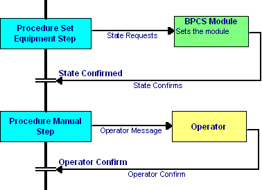
When procedure steps request equipment to do something they can do so by sending a State Request
A State Request is much like a control loop's Set Point. The PID controller (a type of Basic Control) then adjusts control valves etc to keep a Measurement at the Set Point, or within some limits.
With higher levels such as Equipment Modules or Units, Basic Control Loops and Logic can run to move the process in the desired state and then keep it there, indicating so via an interface back to the procedure.
Procedures could set State Request in peer or lower level physical model entities
So, a Unit level Procedure may set the state of the Unit
Or it may set the state of Equipment in the Unit or of Control Modules in the Unit
They should never set the state of higher level entities
So a Unit level procedure should never set a Plant Area State or set the State of another Unit or an EM or CM that is outside the unit.
And for designing the Procedures it would provide a simple view without the complexity of showing the Module Logic
This shows how a procedure might look as a PFC
A current question is "Where should the boundary be between Procedural Control and Basic Control?"
I think we should start from an operational viewpoint and consider where the Operator interacts with Procedures.
Clearly, when a procedure is being run by an operator it would be unfriendly to say the least if the system had no tolerance of delays in the operators response
Now, that to me implies that the Process should be in a stable state whenever an operator input is requested.
And I think it should apply even if the Procedure is running automatically, in effect replacing the operator.
So I propose that the following apply
Procedures steps that interface with Equipment should do so by via Persistent Process States - Where a Persistent Process State:
Is a State that is set entirely by Basic Control and that can be maintained without operator intervention
Can persist for a time, for example longer than the slowest operator response or until some resource runs out
When procedure steps request equipment to do something they can do so by sending a State Request
A State Request is much like a control loop's Set Point. The PID controller (a type of Basic Control) then adjusts control valves etc to keep a Measurement at the Set Point, or within some limits.
With higher levels such as Equipment Modules or Units, Basic Control Loops and Logic can run to move the process in the desired state and then keep it there, indicating so via an interface back to the procedure.
Procedures could set State Request in peer or lower level physical model entities
So, a Unit level Procedure may set the state of the Unit
Or it may set the state of Equipment in the Unit or of Control Modules in the Unit
They should never set the state of higher level entities
So a Unit level procedure should never set a Plant Area State or set the State of another Unit or an EM or CM that is outside the unit.
And for designing the Procedures it would provide a simple view without the complexity of showing the Module Logic
This shows how a procedure might look as a PFC
Friday, 3 June 2011
ISA106 procedures
Thoughts on the emerging ISA106 standard. And S88 phases.
What can a step in an ISA106 procedure do?
Ask the operator to do something, from setting up equipment to entering data to confirming that a manual or paper procedure has been completed
Request equipment to do something for example run an equipment procedure or set equipment to a state
Set up something such as set points for control loops
Record some data
By the way that looks like just the sort of thing an S88 batch manager recipe procedure step can do - but of course ISA 106 people don't seem to like S88's' batchness' Comment please.
Let’s look at the second, asking equipment do something and setting equipment states.
What is the difference? If you ask equipment to do something then the equipment might do numerous things and then say Done.
If you set equipment to a state the equipment might still do several things in the process before it says State Established.
There really is no difference in terms of interfacing a procedure with equipment control, but the first of these may run a longer and more process oriented sequence - and in turn set the equipment to states.
Let’s call the 'Do something please' equipment step a phase (following S88 terms).
Because it is run in the equipment - ie by the BPCS (Basic Process Control System ) that controls the equipment , let’s call it an Equipment phase (or if you like an Equipment Procedural Entity) The Equipment phase itself runs a sequence of setting equipment states with transitions (cf feedback) to direct the steps and confirm that the process actions are achieved.
The Phase could of course set all the individual devices one by one (a common practise). Or it could set a state in a higher level physical entity, provided that entity can in turn set the lower levels devices.
That is what Equipment State Matrices are about – they are deployed in the Dow/ABB State Based Control paper (see Tables 1 and 2) and by most ControlDraw users - and they are highly advantageous. Why?
If you don’t know what they are you can look for them on google
They provide logic where all requested states are known easily. And as many states may be used more than once by different steps and even different by procedures they are more efficient. Alarms can be enabled according to the state matrix, Control loops modes set and so on.
In fact part of the Dow/ABB State Based Control paper is about this, and as I blogged before nothing to do with the S88 model where a recipe (cf procedure) speaks to the equipment. And I do mean Speak, since the objective of part 1 was in part to ensure that chemists (and their recipes) could speak to control engineers (and their equipment controls)
I feel that so far S106 is neglecting State Based Control.
Sunday, 22 May 2011
Pharmaceutical Fermenter Equipment Modules
I have recently been looking at ControlDraw models for large scale Pharmaceutical Fermenter Units from 4 different companies. Process wise, all the fermenters are broadly similar, but each client has their own way!
I cannot publish them because because they are confidential, agreements signed!
I cannot publish them because because they are confidential, agreements signed!
However I have summarised them using some statistics from the models.

Some differences are immediately apparent.
Why is the IO Count for Client 3 so low? This is because they do not use limit switches on their valves. This is something I have never understood as it seems to me that any cost savings would be obliterated by the downtime cause by the inablity to quickly diagnose valve failures.
Why do Clients 1 and 3 have so many parameters? I think that this is in part because they do not distinguish between critical parameters (that can be changed to define the product or CIP ) and other parameters
Actually the differences are greater than they appear, mostly because of different ways of handling routing and cleaning.
What they all have in common is Equipement modules for:
Agitator Control
CIP / SIP
Dissolved Oxygen Control
Exhaust Filter
Gas Feed
Inoculation Transfer
Media Supply
pH Control
Pressure Control
Product Transfer
Sampling
Temperature Control
Some of the models are Unit Centric (the EM's are driven to states by a Unit Level phase) and some are EM Centric where the EM's run phases in parallel with each other. The former approach is my preference as it results in less complexity
Subscribe to:
Comments (Atom)